PCB design · Minebea Intec GmbH · Jan–Apr 2025 & June–July 2026
PR5170 PCB design
Selected PCB work for industrial weighing instruments, including measurement, power, communication, and interface boards.
PCB design & circuit analysis
Altium Designer · Analog circuits · RS232 / RS485 · Power electronics
 Load cell input / acquisition / reference
Selected PCB design examples
Across my two work periods at Minebea Intec, I designed or modified more than 20 PCBs. The examples below highlight selected PR5170 mainboards and a shared power and interface board. Both analog and digital mainboards have standard-environment versions, alongside Ex ec versions for gas Zone 2 applications.
My work: Designed the selected PR5170 mainboard variants and shared baseboard, from signal conditioning to field interfaces.
PR5170 hardware assembly example
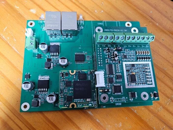
Proprietary details have been obfuscated for confidentiality. Selected works displayed with permission.
Analog weighing mainboard
V1.3B · Jun – Jul 2026Load cells produce small differential signals. Cable voltage drop, excitation changes, and noise can affect the measurement before software sees it. The design also needs to accommodate four- and six-wire sensors and communicate with other equipment.
- Used remote sense returns and an OP2177-based reference proportional to sensed excitation, making the measurement ratiometric.
- Applied symmetrical filtering to the two measurement branches and separated analog supply functions from logic regulation.
- Provided independent RS232 and RS485 UART paths, with selectable termination, biasing, and interface protection.
Analog-input mainboard layouts
Two analog-input mainboard variants: a standard-environment version and an Ex ec version for gas Zone 2 applications.
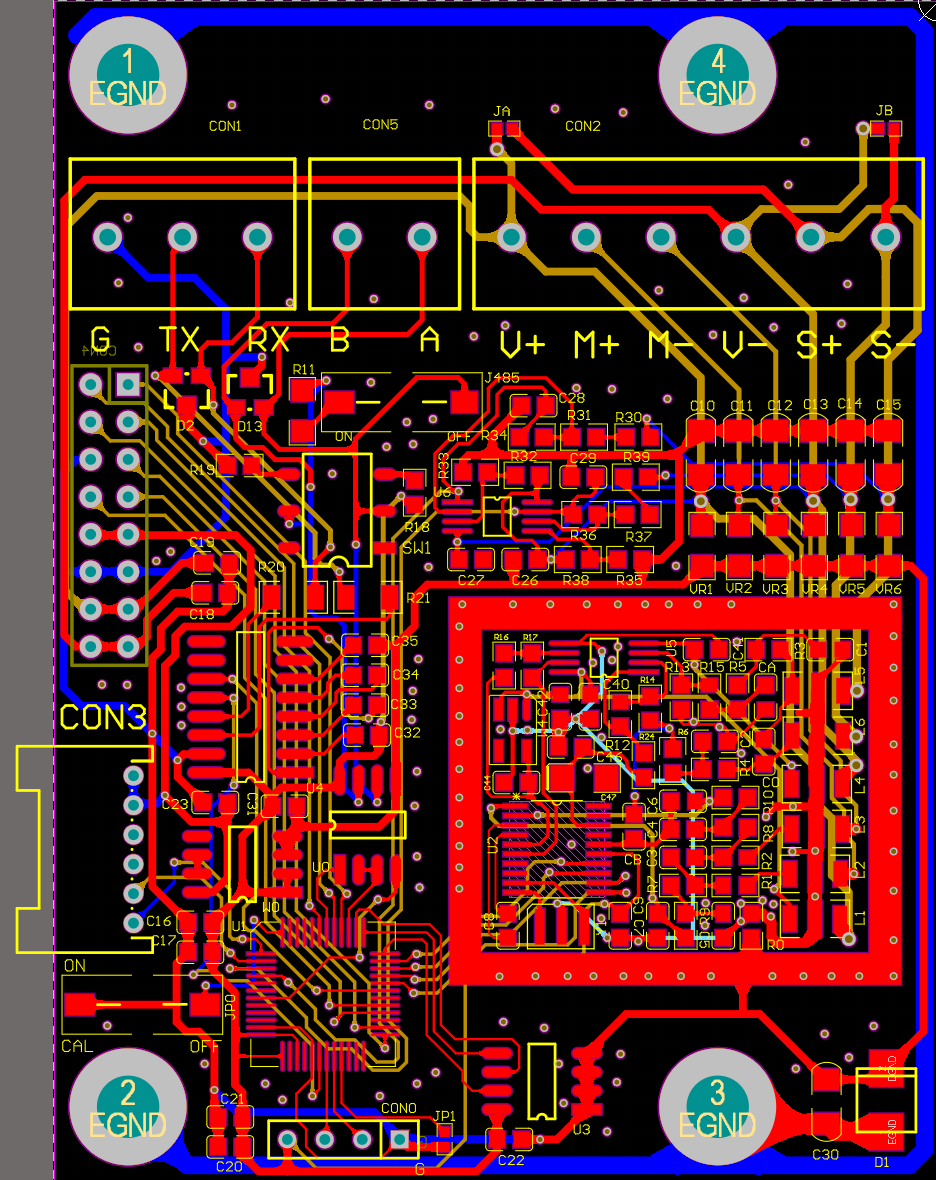
Standard-environment version
Standard-environment layout for the analog-input mainboard, combining sensor input, signal acquisition, control, and communication interfaces.
View full-size layout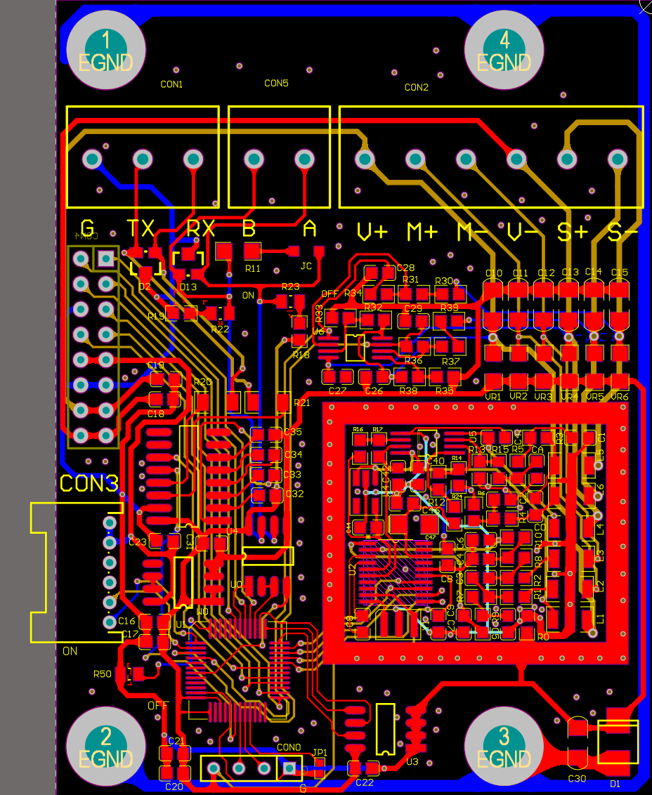
Gas Zone 2 version · Ex ec
Analog-input mainboard layout for Ex ec instrument configurations in gas Zone 2 hazardous areas, providing analog signal acquisition and control.
View full-size layoutDesign details & validation
Sense at the sensor
Six-wire connections send excitation to the sensor and return measurement and remote sense separately. The reference can therefore follow the excitation available at the sensor. Four-wire connections use local jumpers to sense excitation at the board; they do not retain independent remote sensing of cable voltage drop.
Design across board boundaries
A shared interconnect carries power and access to baseboard network and current-output functions. Keeping the mainboard focused on acquisition and control supports reuse of the power and interface baseboard.
Recorded results
- Completed the v1.3b schematic design and documented the signal, reference, power, and communication paths.
- Provided four- and six-wire sensor connection options within the same mainboard architecture.
The supporting material documents circuit architecture and design analysis. Measured noise, weighing accuracy, and temperature drift are not established by these records.
Digital weighing mainboard
V2.0A · Jun – Jul 2026Different field devices require different physical interfaces. The controller needed flexible receive selection, predictable half-duplex bus behavior, and configurable termination and biasing without duplicating the entire instrument platform.
- Provided two field channels, each exposing RS232 and RS485 connections, with mechanical selection of the UART receive source.
- Used MCU-controlled direction on the MAX1487 channel and hardware AutoDirection on the MAX13487 channel.
- Retained nonvolatile configuration, programming access, and compatibility with the shared power and industrial-interface baseboard.
Digital mainboard layouts
Two mainboard variants for external digital weighing platforms: a standard-environment version and an Ex ec version for gas Zone 2 applications.
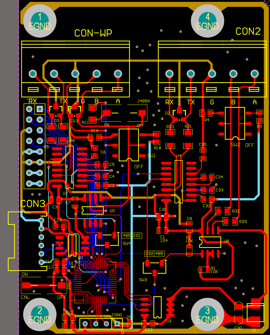
Standard-environment version
Standard-environment mainboard layout for external digital weighing platforms, with serial communication interfaces and controller circuitry.
View full-size layout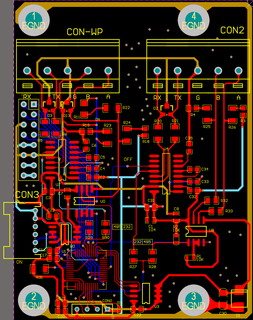
Gas Zone 2 version · Ex ec
Digital mainboard layout for Ex ec instrument configurations in gas Zone 2 hazardous areas, providing controller and serial interfaces for digital weighing platforms.
View full-size layoutDesign details & validation
Two ways to control the bus
The first RS485 channel leaves direction control to firmware. The second uses MAX13487 AutoDirection to reduce the need for a dedicated MCU direction-control signal. The two channels therefore have different integration requirements.
Make selection behavior explicit
Each channel shares its transmit signal across physical layers while the switch selects the receive source. The design does not assume that selecting one interface electrically disconnects every part of the other.
Recorded results
- Completed the digital-mainboard design, including configurable serial interfaces and EEPROM storage.
- Prototype checks recorded normal operation across the tested serial modes, receive-switch positions, termination/bias settings, and the short EEPROM bus.
The reports record specific prototype checks. Broader environmental and EMC qualification is outside those checks. A proposed baseboard voltage adjustment is not represented as a completed change.
Power & industrial interface board
POWER23 V1.4 · Jun – Jul 2026The baseboard needs several supply domains, external network connectivity, and a protected current-loop output. Its isolation boundaries and return paths must remain clear while the same interface supports two different mainboards.
- Separated the main supply conversion path from the nominal 3.3 V network-module supply.
- Provided a plug-in industrial Ethernet module interface, dual RJ45 connectors, status indication, and interface protection.
- Implemented the current-output isolation boundary with optocouplers and an isolated DC/DC supply, followed by the 4–20 mA output circuit.
Shared baseboard layouts
Both layouts provide the same functions. Only component placement changes to suit different mechanical enclosures.
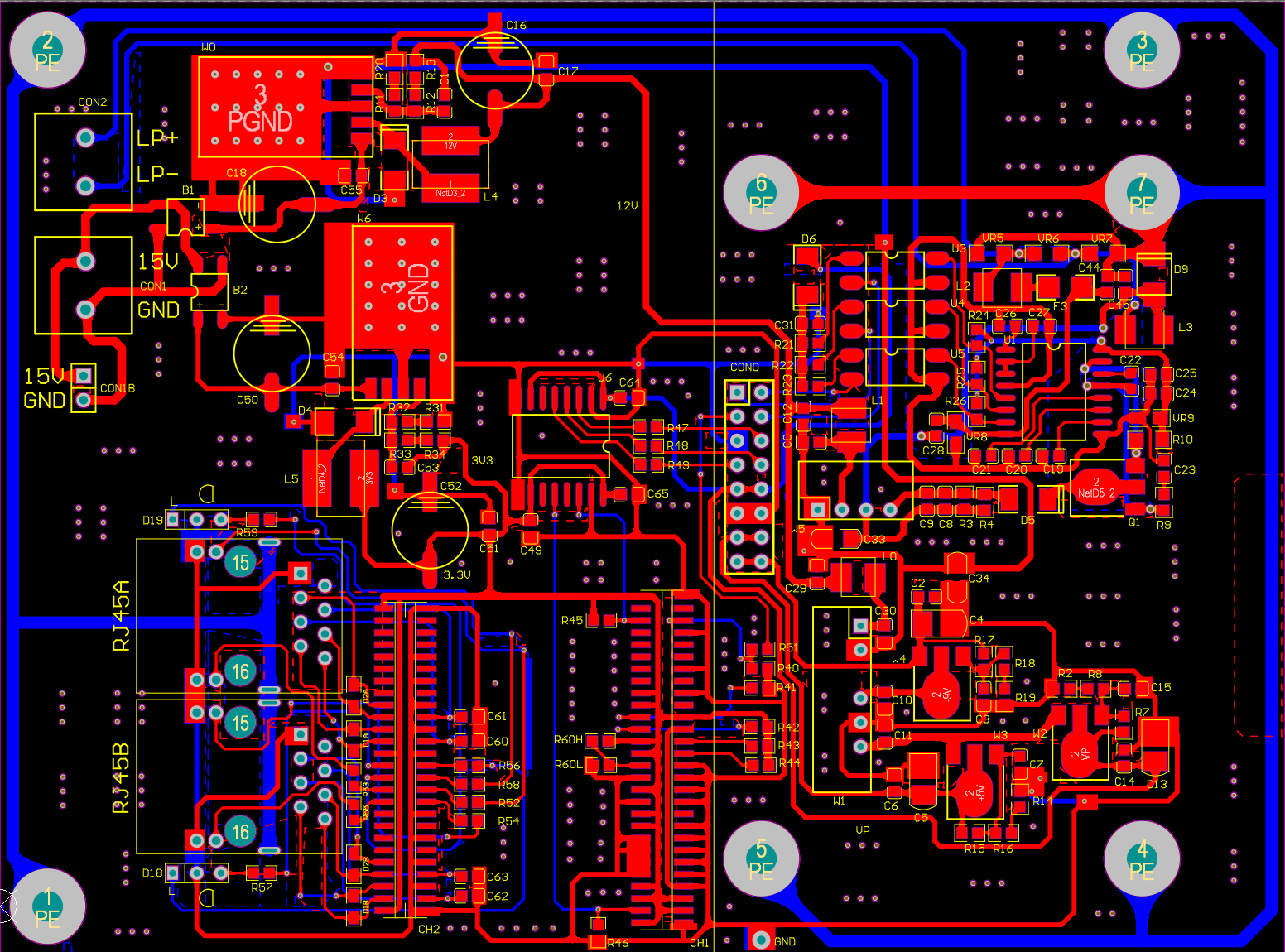
Baseboard Type 1
First component-placement arrangement of the shared power and industrial-interface baseboard, for one mechanical enclosure. Functionally identical to Type 2.
View full-size layout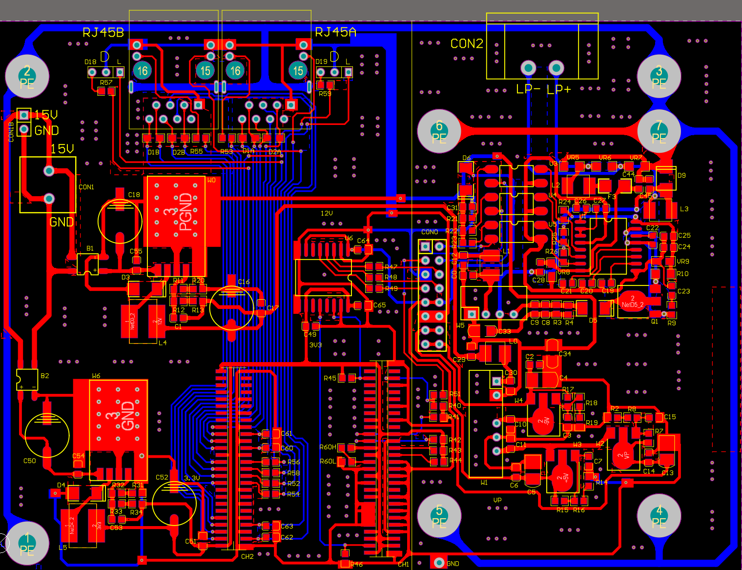
Baseboard Type 2
Alternative component placement for a different mechanical enclosure. The electrical functions are identical to Type 1.
View full-size layoutDesign details & validation
Isolate the right boundary
The current output uses PC817B optocouplers and a B1209S-1W supply. The ADUM1401C elsewhere in the circuit uses a common ground for level conversion and buffering; it is not described as system galvanic isolation.
Reuse the baseboard
Both analog and digital mainboards share the baseboard signal set. The modular architecture keeps power, industrial networking, and analog-output functions separate from the measurement-source decision.
Recorded results
- Completed the power and interface architecture shared by the two mainboard options.
- Prototype documentation records checks at 4 mA, 12 mA, and 20 mA with no abnormalities reported.
The recorded output checks do not establish a numerical accuracy tolerance or maximum load. Network protocol capabilities depend on the installed module and are not specified here.
What the work delivered
Completed schematic designs for the selected analog and digital mainboards and shared power/interface board. Documentation records selected serial-interface and 4–20 mA prototype checks; broader accuracy and environmental qualification are outside those records.